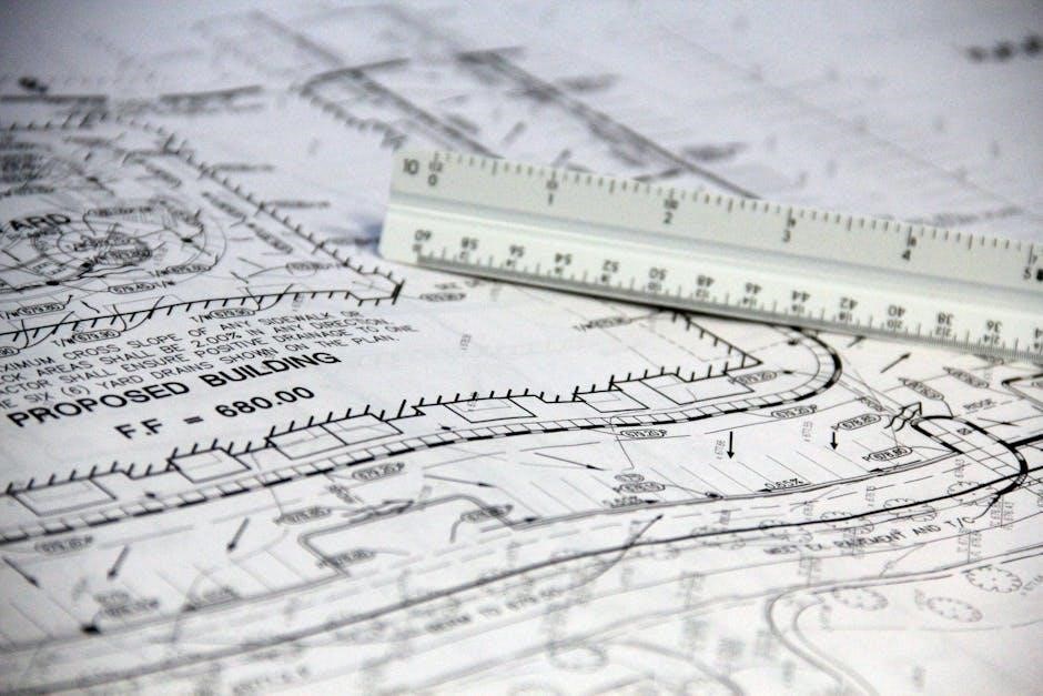
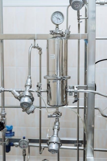
Piping and Instrumentation Diagrams (P&IDs) are schematic representations of industrial processes‚ detailing equipment‚ piping‚ and instrumentation. They are essential for designing‚ operating‚ and maintaining plants safely and efficiently.
1.1 Definition and Purpose of P&IDs
Piping and Instrumentation Diagrams (P&IDs) are detailed schematic representations of industrial processes. They define the piping‚ equipment‚ and instrumentation used to control and monitor operations. The primary purpose of P&IDs is to provide a clear visual representation of a system‚ ensuring safe design‚ operation‚ and maintenance. They serve as a universal communication tool for engineers‚ operators‚ and stakeholders to understand process flow and functionality effectively.
1.2 Importance of P&IDs in Industrial Processes
P&IDs are critical for ensuring process safety‚ efficiency‚ and compliance. They provide a detailed visual representation of industrial systems‚ aiding in design‚ operation‚ and maintenance. These diagrams are essential for troubleshooting‚ training‚ and regulatory compliance. By standardizing process flow and equipment interactions‚ P&IDs minimize risks‚ enhance communication‚ and optimize plant performance‚ making them indispensable in modern industrial operations and decision-making processes.

Common Symbols Used in P&IDs
P&IDs use standardized symbols for equipment‚ instrumentation‚ and flow lines. These symbols represent components like valves‚ pumps‚ and controllers‚ ensuring clear communication and accurate process representation across industries.
2.1 Equipment Symbols
Equipment symbols in P&IDs represent physical components like pumps‚ tanks‚ heat exchangers‚ and valves. These symbols are standardized to ensure clarity and consistency across industries. They visually depict the type and function of each piece of equipment‚ aiding in process design‚ operation‚ and maintenance. Accurate representation of equipment is crucial for understanding system layout and flow. Proper use of symbols enhances readability and reduces errors. They are essential for effective communication among engineers and technicians.
2.2 Instrumentation and Control Symbols
Instrumentation and control symbols in P&IDs denote sensors‚ actuators‚ and control devices. These symbols‚ such as flow meters‚ pressure gauges‚ and valves‚ illustrate how processes are monitored and regulated. They provide detailed insights into automation and safety systems‚ ensuring precise control over industrial operations. Standardization of these symbols is vital for clear communication and efficient system management across engineering teams and industries.

Understanding P&ID Lines and Connections
P&ID lines represent material flow‚ while connections link equipment and instruments. Clear differentiation between piping and instrumentation lines ensures process clarity and operational safety‚ adhering to industry standards.
3.1 Piping and Flow Lines
Piping and flow lines in P&IDs represent the physical pathways for materials and energies. They are differentiated by line types‚ such as solid or dashed‚ and may include arrows to indicate flow direction. These lines connect equipment‚ valves‚ and instruments‚ providing a clear visual of the process flow and material movement within the system‚ ensuring operational clarity and safety standards.

3.2 Instrumentation and Control Lines
Instrumentation and control lines in P&IDs represent connections between instruments‚ sensors‚ and control systems. These lines are typically dashed or dotted‚ often color-coded‚ to differentiate them from piping. They illustrate communication paths for data transmission‚ such as sensor readings or control signals‚ ensuring precise monitoring and automation of industrial processes‚ which is critical for maintaining operational efficiency and safety standards effectively.

Annotations and Labels in P&IDs
Annotations and labels provide clarity to P&IDs‚ ensuring components are easily identified. They include tags‚ notes‚ and references‚ enhancing understanding and compliance with safety and operational standards.
.
4.1 Tagging and Labeling Conventions
Tagging and labeling conventions in P&IDs ensure consistency and clarity. Equipment and instruments are labeled with unique identifiers‚ following industry standards. This uniformity aids in quick identification‚ maintenance‚ and operational efficiency‚ reducing errors and enhancing safety across industrial processes.
4.2 Notes and References
Notes and references in P&IDs provide additional context and compliance information. They include standards‚ abbreviations‚ and legends‚ ensuring clarity. Software tools like M4 P&ID FX 7.2 support dynamic updates‚ enhancing accuracy. These elements are crucial for preventing errors and ensuring adherence to safety protocols in industrial processes.

Creating and Interpreting P&ID Symbols
Creating and interpreting P&ID symbols involves using advanced software and automation tools. These enable efficient design‚ modification‚ and analysis‚ ensuring clarity and functionality for engineers.
5.1 Tools and Software for P&ID Development
Modern tools like M4 P&ID FX 7.2 and YOLOv8 enable efficient P&ID creation. These software solutions offer dynamic symbols‚ improved renumbering‚ and streamlined template management. They support automation‚ enhancing productivity and accuracy in designing and updating diagrams. Such tools are essential for engineers to ensure clear and functional representations of industrial processes.
5.2 Best Practices for Clear Representation
Best practices for clear P&ID representation include using standardized symbols‚ consistent labeling‚ and organized layouts. Adhering to industry standards ensures consistency and clarity. Proper documentation‚ such as notes and legends‚ helps clarify symbols and conventions. Regular updates and maintenance of P&IDs are crucial to reflect process changes accurately. Utilizing advanced software tools like M4 P&ID FX 7.2 and YOLOv8‚ along with proper training‚ enhances diagram effectiveness. Collaborative reviews with stakeholders ensure error-free and high-quality diagrams.

Applications of P&IDs in Various Industries
P&IDs are essential in oil‚ gas‚ chemical‚ power‚ and water treatment industries for process design‚ safety‚ and maintenance‚ ensuring efficient and safe plant operations.
6.1 Oil‚ Gas‚ and Chemical Industries
P&IDs are critical in oil‚ gas‚ and chemical industries for process design‚ safety‚ and maintenance. They provide detailed overviews of process flow‚ equipment‚ and instrumentation‚ ensuring safe operations and regulatory compliance. These diagrams are essential for troubleshooting‚ modifications‚ and training‚ playing a vital role in plant operations and project lifecycle management.
6;2 Power Generation and Water Treatment
P&IDs are vital in power generation and water treatment for process design‚ safety‚ and maintenance. They ensure efficient operations and compliance with regulations. In power plants‚ P&IDs map steam‚ water‚ and fuel flows‚ while in water treatment‚ they detail purification and distribution processes‚ aiding in monitoring and control to maintain water quality and safety.
Automation and Digitalization in P&IDs
Automation tools enhance P&ID management with dynamic symbols‚ improved renumbering‚ and streamlined template management‚ ensuring accuracy and efficiency in process design and documentation.
7.1 Modern Software for P&ID Automation

Modern software like M4 P&ID FX 7.2 offers dynamic symbols‚ renumbering‚ and template management‚ enhancing P&ID creation. Tools utilize object detection‚ such as YOLOv8‚ for automating symbol identification‚ improving efficiency and accuracy in diagram updates and plant operations.
7.2 Future Trends in P&ID Development
Future P&ID development will focus on AI integration‚ automating symbol recognition‚ and enhancing collaboration through cloud-based platforms. Tools like YOLOv8 will improve object detection‚ enabling smarter workflows. Additionally‚ AR/VR integration and real-time data synchronization will revolutionize diagram interaction and updates‚ ensuring efficiency and accuracy in industrial processes.
Sustainability-focused P&ID tools will also emerge‚ incorporating energy-efficient designs and emissions tracking‚ aligning with global environmental goals.

Standards and Guidelines for P&IDs
P&IDs must comply with industry standards like ISA and ASME. These guidelines ensure consistent symbol usage‚ clear documentation‚ and adherence to safety protocols for reliable process representation.
8.1 Industry Standards for Symbol Usage
Industry standards like ISA-5.1 and ASME define specific symbols for P&IDs‚ ensuring consistency across industries. These standards detail graphical representations for equipment‚ valves‚ and instruments‚ promoting clarity and uniformity in process documentation.
8.2 Compliance and Safety Regulations
Compliance with safety regulations‚ such as OSHA and IEC standards‚ is crucial for P&IDs. Adherence ensures accurate representation of safety systems‚ hazard controls‚ and emergency shutdowns‚ reducing risks and ensuring regulatory compliance.
P&IDs are vital for process safety and efficiency. For further learning‚ explore industry standards‚ tutorial guides‚ and software manuals to master P&ID creation and interpretation.
9.1 Summary of Key Concepts
P&IDs are detailed diagrams representing industrial processes‚ showing equipment‚ piping‚ and instrumentation. They ensure process safety‚ efficiency‚ and compliance. Symbols standardize representation‚ aiding communication among engineers. Understanding P&IDs is crucial for design‚ operation‚ and maintenance. They integrate with modern software for automation and digitalization‚ enhancing accuracy and productivity in various industries.
9.2 Recommended Resources for Further Learning
Explore ISA and ANSI standards for comprehensive symbol libraries. Utilize textbooks on P&ID design and online tutorials for practical insights. Industry-specific guides and software manuals‚ like M4 P&ID FX‚ offer hands-on learning. Engage with online forums and communities for real-world applications and troubleshooting.
